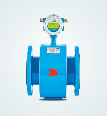
Electromagnetic Flowmeter
MagFlow 6415
Inline Mains Operated
Introduction
Electromagnetic Flowmeters are based on Faraday’s Law of Electromagnetic Induction.
In an Electromagnetic Flowmeter, the magnetic field is generated by a set of coils. As the conductive liquid passes through the electromagnetic field, an electric voltage is induced in the liquid which is directly proportional to its velocity. This induced voltage is perpendicular to both, the liquid flow direction and the electromagnetic field direction. The voltage sensed by the electrodes is further processed by the transmitter to give standardised output signal or displayed in appropriate engineering unit.
The flux density of the electromagnetic field in a given Flowmeter and the distance between the electrodes are constant. Therefore, the induced voltage is only a function of liquid velocity.
Salient Features
Based on Faraday’s law of electromagnetic induction
Coil assembly in hermetically sealed welded construction
High linearity due to characteristic magnetic field
High long-term stability and reliability
Flow tube sizes 10 mm to 2000 mm and above
Integral or remote transmitter
Field interchangeable electronics
Absolute zero stability and noise elimination due pulsed DC excitation

Applications
Chemical, petrochemical and process industries
Food and drug industries
Paper and pulp industries
Dredging industries
Fertilizers industries
Pharmaceutical industries
Sugar, beverage industries
Water and waste water management
Mining industries
Salient Features
![]() Based on Faraday’s law of electromagnetic induction
Based on Faraday’s law of electromagnetic induction
![]() Coil assembly in hermetically sealed welded construction
Coil assembly in hermetically sealed welded construction
![]() High linearity due to characteristic magnetic field
High linearity due to characteristic magnetic field
![]() High long-term stability and reliability
High long-term stability and reliability
![]() Flow tube sizes 10 mm to 2000 mm and above
Flow tube sizes 10 mm to 2000 mm and above
![]() Integral or remote transmitter
Integral or remote transmitter
![]() Field interchangeable electronics
Field interchangeable electronics
![]() Absolute zero stability and noise elimination due pulsed DC excitation
Absolute zero stability and noise elimination due pulsed DC excitation
Applications
![]() Chemical, petrochemical and process industries
Chemical, petrochemical and process industries
![]() Food and drug industries
Food and drug industries
![]() Paper and pulp industries
Paper and pulp industries
![]() Dredging industries
Dredging industries
![]() Fertilizers industries
Fertilizers industries
![]() Pharmaceutical industries
Pharmaceutical industries
![]() Sugar, beverage industries
Sugar, beverage industries
![]() Water and waste water management
Water and waste water management
![]() Mining industries
Mining industries
Product Selection Guide
| Parameters | MagFlow 6415 |
|---|---|
| Nominal dia (mm) | 10 to 2000 |
| Working pressure (kg/cm2) | 10, 16, 25, 40 |
| Working temperature | Integral PTFE – 120°C Remote PTFE – 180°C Others – 70°C |
| Electrode material | SS 316L Std.* |
| Sensor lining | Std. Rubber* |
| Display version | Integral/Remote |
| Measuring tube material | SS 304 Std.* |
| Sensor housing material | Std. CS* |
| End connection | Flange/Wafer/Tri-clamp/SMS |
| Flange standard | ANSI 150* |
| Measuring range | 0.2 to 12 m/sec. Bidirectional |
| Accuracy % of measured value | ±O.5% (±O.2% consult factory) |
| Repeatability | ±0.2% of Span |
| Display | Graphic LCD |
| Display units | All standard engineering units in m³, litre, gallon, ft³, imperial gallon |
| Output | Std. 4 – 20 mA, Pulse, RS 485 |
| Dual power supply | 12 – 60 V DC or 80 – 300 V AC/DC |
| Protection class for sensor | Std. IP 67 Option IP 68 for flow tube in remote type |
| Protection class for transmitter | IP 67 |
| Cable length for remote | Std. 10 m* |
| Grounding | Built-in electrode |
| Installation | Inline |